Buffer Cell: Difference between revisions
Created page with "{{Block |image=Buffer_Cell_256.png |invimage= Buffer Cell |type=Multipart block |dirt=Support block |gravity=No |transparent=Yes <small>(partial)</small> |light=Yes, 7 |tool=a..." |
No edit summary |
||
| (One intermediate revision by the same user not shown) | |||
| Line 12: | Line 12: | ||
|availability=Survival | |availability=Survival | ||
|firstver=v4.0.0 | |firstver=v4.0.0 | ||
| | |data=25 | ||
|multipartid=pr_agate | |||
|nameid=None | |||
}} | }} | ||
The '''Buffer Cell''', is an array [[Logic Gate|logic gate]]. Array gates | The '''Buffer Cell''', is an array [[Logic Gate|logic gate]]. Array gates have gate logic as well as 1 or more pass-through wires. They are also slightly taller than normal gates. | ||
== Obtaining == | == Obtaining == | ||
| Line 30: | Line 32: | ||
== Usage == | == Usage == | ||
=== I/O === | === I/O === | ||
The Buffer Cell has a total of 4 inputs outputs. All IOs in this gate act as wires. The wire connecting the front and back is the '''bottom wire''' and the left and right wire is the '''top wire'''. | The Buffer Cell has a total of 4 inputs and outputs. All IOs in this gate act as wires. The wire connecting the front and back is the '''bottom wire''' and the left and right wire is the '''top wire'''. | ||
=== Logic === | === Logic === | ||
The Buffer cell acts much like 2 separate [[Wire|wires]] in a single block. This gate can allow one 'wire' to transverse between the front and back, and the other between left and right without crossing the signals. If the bottom wire is powered, a signal is conducted upwards to the top wire. When the bottom one is unpowered, the top returns to its natural state. Unlike traditional gates, there is no delay when passing a signal between inputs; it functions identically to wires. | The Buffer cell acts much like 2 separate [[Wire|wires]] in a single block. This gate can allow one 'wire' to transverse between the front and back, and the other between left and right without crossing the signals. If the bottom wire is powered, a signal is conducted upwards to the top wire. When the bottom one is unpowered, the top returns to its natural state. Unlike traditional gates, there is no delay when passing a signal between inputs; it functions identically to wires. | ||
Latest revision as of 17:06, 17 March 2015
| Type |
Multipart block |
|---|---|
| Physics |
No |
| Transparency |
Yes (partial) |
| Luminance |
Yes, 7 |
| Blast resistance | |
| Tool |
Any tool |
| Renewable |
Yes |
| Stackable |
Yes (64) |
| Flammable |
No |
| Availability |
Survival |
| First appearance | |
| Drops |
Itself |
| Data value |
dec: 25 hex: 19 bin: 11001 |
| Multipart ID |
pr_agate |
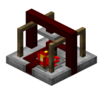
The Buffer Cell, is an array logic gate. Array gates have gate logic as well as 1 or more pass-through wires. They are also slightly taller than normal gates.
Obtaining
Crafting
Lua error: callParserFunction: function "#dplvar" was not found.
Usage
I/O
The Buffer Cell has a total of 4 inputs and outputs. All IOs in this gate act as wires. The wire connecting the front and back is the bottom wire and the left and right wire is the top wire.
Logic
The Buffer cell acts much like 2 separate wires in a single block. This gate can allow one 'wire' to transverse between the front and back, and the other between left and right without crossing the signals. If the bottom wire is powered, a signal is conducted upwards to the top wire. When the bottom one is unpowered, the top returns to its natural state. Unlike traditional gates, there is no delay when passing a signal between inputs; it functions identically to wires.
History
| Version | Changes |
|---|---|
| v4.0.0 | Added the Buffer Cell. |
Issues
Issues pertaining to "Buffer Cell" are maintained on the ProjectRed Github page. Report issues there.


