RS Latch: Difference between revisions
(Created page with "{{Block |image=RS_Latch_256.png |invimage=RS Latch |type=Multipart block |dirt=Support block |gravity=No |transparent=Yes <small>(partial)</small> |light=Yes, 7 |tool=any |sta...") |
No edit summary |
||
| (5 intermediate revisions by the same user not shown) | |||
| Line 12: | Line 12: | ||
|availability=Survival | |availability=Survival | ||
|firstver=v4.0.0 | |firstver=v4.0.0 | ||
| | |data=12 | ||
|multipartid=pr_igate | |||
|nameid=None | |||
}} | }} | ||
The '''RS Latch''' is a | The '''RS Latch''', also known as the ''SR Latch'', is a sequential [[Logic Gate|logic gate]] with 4 inputs and 2 outputs. The name stands for ''Set Reset Latch''. This is the fundamental gate used to create digital memory, as it can store the state of 1 bit (on or off). | ||
== Obtaining == | == Obtaining == | ||
| Line 30: | Line 32: | ||
== Usage == | == Usage == | ||
=== I/O === | === I/O === | ||
The | The RS Latch has 2 input and 4 outputs. When placed, on the ground, the left and right function both as inputs and outputs, while the front and back are just outputs. The left and right sides are the '''selectors''' while the front and back are '''state outputs'''. | ||
=== Logic === | === Logic === | ||
The whole idea of the RS Latch is as follows. There are 2 ''' | The whole idea of the RS Latch is as follows. There are 2 states, each one consisting of a '''selector''' and a '''state output'''. The selectors control which of the 2 states is active. When a state is selected, its output will remain on until the other one is selected. Selecting the same state multiple times has no effect. | ||
The RS Latch has 2 different modes. In '''mode 1''', the ''selectors'' also function as ''state outputs'', meaning that if their respective state output is active, they themselves will also emit a signal. In '''mode 2''', the selectors do not function as state outputs. | |||
=== Configuration === | === Configuration === | ||
A shift-right-click with a [[Screwdriver|screwdriver]] can change the settings on the gate. When placed, the RS Latch is on ''mode 1''. The first click will flip which side (front or back) each ''selector input'' is tied to. A second click will change it to ''mode 2''. A third click will flip ''mode 2''. After that, it will reset to unflipped ''mode 1''. | |||
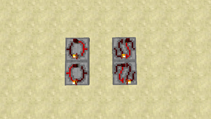
[[File:rslatch_modesr.png|center|425px|thumbnail|The four states of an RS Latch. The bottom ones are | [[File:rslatch_modesr.png|center|425px|thumbnail|The four states of an RS Latch. The bottom ones are ''flipped''. The 2 on the left are ''mode 1'' while the 2 on the right are ''mode 2''.]] | ||
==History== | ==History== | ||
| Line 45: | Line 48: | ||
|- | |- | ||
| v4.0.0 | | v4.0.0 | ||
| Added the | | Added the RS Latch. | ||
|- | |||
| v4.5.9 | |||
| Fixed bug that caused the state to stick when in flipped modes | |||
|} | |} | ||
== Issues == | == Issues == | ||
{{Issues}} | {{Issues}} | ||
Latest revision as of 19:35, 17 March 2015
| Type |
Multipart block |
|---|---|
| Physics |
No |
| Transparency |
Yes (partial) |
| Luminance |
Yes, 7 |
| Blast resistance | |
| Tool |
Any tool |
| Renewable |
Yes |
| Stackable |
Yes (64) |
| Flammable |
No |
| Availability |
Survival |
| First appearance | |
| Drops |
Itself |
| Data value |
dec: 12 hex: C bin: 1100 |
| Multipart ID |
pr_igate |
The RS Latch, also known as the SR Latch, is a sequential logic gate with 4 inputs and 2 outputs. The name stands for Set Reset Latch. This is the fundamental gate used to create digital memory, as it can store the state of 1 bit (on or off).
Obtaining
Crafting
| Ingredients | Crafting recipe |
|---|---|
| Anode + Cathode + Conductive Plate + Circuit Plate |
Usage
I/O
The RS Latch has 2 input and 4 outputs. When placed, on the ground, the left and right function both as inputs and outputs, while the front and back are just outputs. The left and right sides are the selectors while the front and back are state outputs.
Logic
The whole idea of the RS Latch is as follows. There are 2 states, each one consisting of a selector and a state output. The selectors control which of the 2 states is active. When a state is selected, its output will remain on until the other one is selected. Selecting the same state multiple times has no effect.
The RS Latch has 2 different modes. In mode 1, the selectors also function as state outputs, meaning that if their respective state output is active, they themselves will also emit a signal. In mode 2, the selectors do not function as state outputs.
Configuration
A shift-right-click with a screwdriver can change the settings on the gate. When placed, the RS Latch is on mode 1. The first click will flip which side (front or back) each selector input is tied to. A second click will change it to mode 2. A third click will flip mode 2. After that, it will reset to unflipped mode 1.
History
| Version | Changes |
|---|---|
| v4.0.0 | Added the RS Latch. |
| v4.5.9 | Fixed bug that caused the state to stick when in flipped modes |
Issues
Issues pertaining to "RS Latch" are maintained on the ProjectRed Github page. Report issues there.


