Bus Transceiver: Difference between revisions
(Created page with "{{Block |image=Bus_Xcvr_256.png |invimage=Bus Tranceiver |type=Multipart block |dirt=Support block |gravity=No |transparent=Yes <small>(partial)</small> |light=No |tool=any |s...") |
No edit summary |
||
| Line 1: | Line 1: | ||
{{Block | {{Block | ||
|image=Bus_Xcvr_256.png | |image=Bus_Xcvr_256.png | ||
|invimage=Bus | |invimage=Bus Transceiver | ||
|type=Multipart block | |type=Multipart block | ||
|dirt=Support block | |dirt=Support block | ||
| Line 15: | Line 15: | ||
}} | }} | ||
The '''Bus | The '''Bus Transceiver''', sometimes referred to as a '''Bus Xcvr''', is a bundled signal [[Logic Gate|logic gate]] with 4 inputs and 2 outputs. | ||
== Obtaining == | == Obtaining == | ||
| Line 24: | Line 24: | ||
|A2= Silicon Chip |B2= Circuit Plate |C2= Silicon Chip | |A2= Silicon Chip |B2= Circuit Plate |C2= Silicon Chip | ||
|A3= Bundled Plate |B3= Bundled Plate |C3= Bundled Plate | |A3= Bundled Plate |B3= Bundled Plate |C3= Bundled Plate | ||
|Output=Bus | |Output= Bus Transceiver | ||
|foot=1 | |foot=1 | ||
}} | }} | ||
| Line 30: | Line 30: | ||
== Usage == | == Usage == | ||
=== I/O === | === I/O === | ||
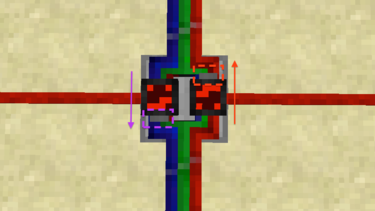
The Bus | The Bus Transceiver has a total of 4 inputs and 2 outputs. When placed, on the ground, the left and right sides of the gate are the left and right '''latch inputs''' while the other 2 are the '''bundled connections'''. Bundled connections will only connect to [[Bundled Cable|bundled cables]]. | ||
=== Logic === | === Logic === | ||
Bundled signals can run from front to back, or from back to front. These two directions are by default blocked, but the corresponding '''latch''' input can enable flow in that direction. By default, the right latch corresponds with back-to-front flow, and the left with front-to-back flow. | Bundled signals can run from front to back, or from back to front. These two directions are by default blocked, but the corresponding '''latch''' input can enable flow in that direction. By default, the right latch corresponds with back-to-front flow, and the left with front-to-back flow. | ||
| Line 47: | Line 47: | ||
|- | |- | ||
| v4.0.0 | | v4.0.0 | ||
| Added the Bus | | Added the Bus Transceiver. | ||
|} | |} | ||
== Issues == | == Issues == | ||
{{Issues}} | {{Issues}} | ||
Revision as of 19:48, 12 April 2014

| Type |
Multipart block |
|---|---|
| Physics |
No |
| Transparency |
Yes (partial) |
| Luminance |
No |
| Blast resistance | |
| Tool |
Any tool |
| Renewable |
Yes |
| Stackable |
Yes (64) |
| Flammable |
No |
| Availability |
Survival |
| First appearance | |
| Drops |
Itself |
| Name |
bus_transceiver |
The Bus Transceiver, sometimes referred to as a Bus Xcvr, is a bundled signal logic gate with 4 inputs and 2 outputs.
Obtaining
Crafting
| Ingredients | Crafting recipe |
|---|---|
| Bundled Plate + Silicon Chip + Circuit Plate |
Usage
I/O
The Bus Transceiver has a total of 4 inputs and 2 outputs. When placed, on the ground, the left and right sides of the gate are the left and right latch inputs while the other 2 are the bundled connections. Bundled connections will only connect to bundled cables.
Logic
Bundled signals can run from front to back, or from back to front. These two directions are by default blocked, but the corresponding latch input can enable flow in that direction. By default, the right latch corresponds with back-to-front flow, and the left with front-to-back flow.
The 2 large display panels on each side of the gate dynamically indicate which signal is active for that side.
Configuration
A shift-right-click with a screwdriver can flip the gate horizontally. When flipped, the gate's latch inputs will swap, at which point the right will correspond with front-to-back signal flow, while the left will correspond with back-to-front signal flow, which is opposite from its default behavior.
The gray blocks attached to each display panel indicate which latch goes with which direction of signal flow.
History
| Version | Changes |
|---|---|
| v4.0.0 | Added the Bus Transceiver. |
Issues
Issues pertaining to "Bus Transceiver" are maintained on the ProjectRed Github page. Report issues there.