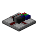
Bus Converter
| Type |
Multipart block |
|---|---|
| Physics |
No |
| Transparency |
Yes (partial) |
| Luminance |
No |
| Blast resistance | |
| Tool |
Any tool |
| Renewable |
Yes |
| Stackable |
Yes (64) |
| Flammable |
No |
| Availability |
Survival |
| First appearance | |
| Drops |
Itself |
| Data value |
dec: 29 hex: 1D bin: 11101 |
| Multipart ID |
pr_bgate |
The Bus Converter, is a bundled logic gate with 4 inputs and 2 outputs, primarily used to convert analog redstone signals (i.e. signals of strength 0-15) to and from their corresponding digital signals (bundled cable colors).
Obtaining
Crafting
Lua error: callParserFunction: function "#dplvar" was not found.
Usage
I/O
The Bus Converter at any given time has a total of 3 outputs and 1 input. When placed on the ground, the left and right sides of the gate are the 2 running outputs. The front is the bundled connection, while the back is the analog connection. Depending on the mode, the front is the input and the back is the output, or vice versa. The bundled connection can only connect to bundled cables.
Logic
The purpose of the bus converter is to change analog redstone signal levels to and from their respected color on the bundled cable spectrum. Signals 0 to 15 are equivalent to colors white to black (i.e. 0 to white, 1 to orange, etc.)
Analog to Digital
By default, the gate is in Analog to Digital mode, which means it will look at the current level of analog signal at its analog input and output the corresponding color on the bundled output in the front of the gate. When the analog input is non-zero, the two running outputs are enabled as well. Note that when there is a zero analog signal as the input, the color white will be enabled. Therefore, there is always at least 1 color being emitted at all times.
Digital to Analog
The second mode is Digital to Analog, in which the gate will take the highest color at the bundled input, and convert it to the corresponding analog output. When the bundled input signal is non-zero, the two running outputs are enabled as well. Note that when the white color is enabled in the bundled input, the output is still zero. That means there is no way to differentiate between a zero bundled input from a white bundled input. This is when the running outputs are handy.
Configuration
A shift-right-click with a screwdriver can swap the conversion modes.
History
| Version | Changes |
|---|---|
| v4.4.6 | Added the Bus Converter. |
| v4.5.15 | Changed so in Analog to Digital mode, a zero input would output a white bundled signal instead of nothing. |
Issues
Issues pertaining to "Bus Converter" are maintained on the ProjectRed Github page. Report issues there.


