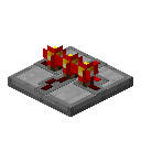
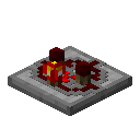
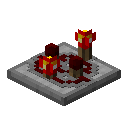
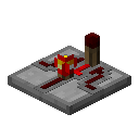
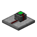
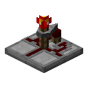
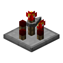
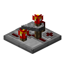
Logic Gate
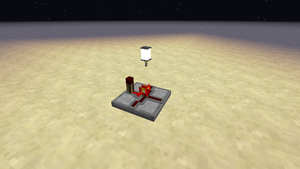
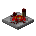
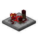
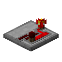
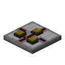
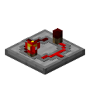
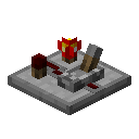
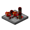
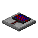
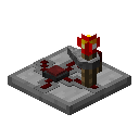
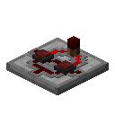
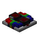
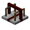
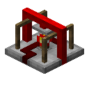
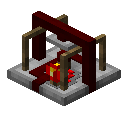
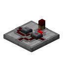
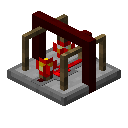
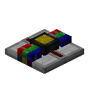
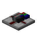
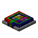
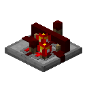
A logic gate is a block in Minecraft that is used to manipulate redstone signals to do many useful things. They play a major role in most redstone circuits. Repeaters and comparators are good examples of logic gates that is already in Minecraft. Gates added by ProjectRed tend to be a lot more useful and flexible.
Mechanics
Basics
A logic gate's purpose is to manipulate redstone signals. They will connect to redstone dust, red alloy wires, or sometimes bundled cables. They also need to be placed on a solid block face. If the root block is removed, gates will break and fall to the ground like repeaters and comparators. All gates can be rotated by right-clicking with the screwdriver on the gate. Some gates are configurable and can be changed by shift-right-clicking with the screwdriver. Logic gates are also multiparts, implemented using Chickenbone's Forge Multipart API. If another multipart is small enough, it can be placed in the same block with the gate.
Inputs and outputs
Each gate can have up to 4 inputs and 4 outputs. The connections can be one of several types:
 |
Digital IOs can connect directly to a source of redstone power. This can be either a strongly powered block, redstone dust, or a redstone alloy wire. Analog IOs can also connect to any source of redstone power, but is also capable of sensing and emitting a signal of a specific analog strength (0 - 15). Bundled IOs will only connect to a bundled cable or another device capable of accepting bundled signal. |
Along with the type of connection, each gate also has a designated side of input or output. These sides are assigned with a number of 0 to 3. 0 is the side that faces away from you when you place the gate on the ground. As you move clockwise around the gate, the number increases. For example, if you are facing north when you place a gate, the side that faces north is 0, east is 1, south is 2, and west is 3.
Index of Gates
Here is a table of all the known gates that are added by ProjectRed Integration. Click on one to see how it works.

