Bus Transceiver: Difference between revisions
(→Logic) |
No edit summary |
||
| Line 12: | Line 12: | ||
|availability=Survival | |availability=Survival | ||
|firstver=v4.0.0 | |firstver=v4.0.0 | ||
| | |data=22 | ||
|multipartid=pr_bgate | |||
|nameid=None | |||
}} | }} | ||
The '''Bus Transceiver''', sometimes referred to as a | The '''Bus Transceiver''', sometimes referred to as a ''Bus Xcvr'', is a bundled signal [[Logic Gate|logic gate]] with 4 inputs and 2 outputs. | ||
== Obtaining == | == Obtaining == | ||
| Line 30: | Line 32: | ||
== Usage == | == Usage == | ||
=== I/O === | === I/O === | ||
The Bus Transceiver has a total of 4 inputs and 2 outputs. When placed, on the ground, the left and right sides of the gate are the left and right '''latch | The Bus Transceiver has a total of 4 inputs and 2 outputs. When placed, on the ground, the left and right sides of the gate are the left and right '''latch''' inputs while the other 2 are the '''bundled connections'''. Bundled connections will only connect to [[Bundled Cable|bundled cables]]. | ||
=== Logic === | === Logic === | ||
Bundled signals can run from front-to-back, or from back-to-front. These two directions are by default blocked, but the corresponding | Bundled signals can run from front-to-back, or from back-to-front. These two directions are by default blocked, but the corresponding ''latch'' input can enable flow in that direction. By default, the right latch corresponds with back-to-front flow, and the left with front-to-back flow. | ||
The 2 large | The 2 large display panels on each side of the gate dynamically indicate which signal is active for that side. | ||
=== Configuration === | === Configuration === | ||
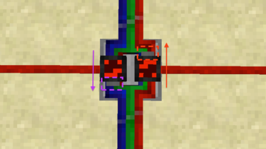
[[File:busxvrflow.png|right|thumb|375px|Directions of flow for the Bus Transceiver|link=]] | [[File:busxvrflow.png|right|thumb|375px|Directions of flow for the Bus Transceiver|link=]] | ||
A shift-right-click with a [[Screwdriver|screwdriver]] can flip the gate horizontally. When flipped, the gate's | A shift-right-click with a [[Screwdriver|screwdriver]] can flip the gate horizontally. When flipped, the gate's ''latch'' inputs will swap, at which point the right will correspond with front-to-back signal flow, while the left will correspond with back-to-front signal flow, which is opposite from its default behavior. | ||
The gray blocks attached to each | The gray blocks attached to each display panel indicate which latch goes with which direction of signal flow. | ||
==History== | ==History== | ||
Latest revision as of 17:00, 17 March 2015

| Type |
Multipart block |
|---|---|
| Physics |
No |
| Transparency |
Yes (partial) |
| Luminance |
No |
| Blast resistance | |
| Tool |
Any tool |
| Renewable |
Yes |
| Stackable |
Yes (64) |
| Flammable |
No |
| Availability |
Survival |
| First appearance | |
| Drops |
Itself |
| Data value |
dec: 22 hex: 16 bin: 10110 |
| Multipart ID |
pr_bgate |
The Bus Transceiver, sometimes referred to as a Bus Xcvr, is a bundled signal logic gate with 4 inputs and 2 outputs.
Obtaining
Crafting
| Ingredients | Crafting recipe |
|---|---|
| Bundled Plate + Silicon Chip + Circuit Plate |
Usage
I/O
The Bus Transceiver has a total of 4 inputs and 2 outputs. When placed, on the ground, the left and right sides of the gate are the left and right latch inputs while the other 2 are the bundled connections. Bundled connections will only connect to bundled cables.
Logic
Bundled signals can run from front-to-back, or from back-to-front. These two directions are by default blocked, but the corresponding latch input can enable flow in that direction. By default, the right latch corresponds with back-to-front flow, and the left with front-to-back flow.
The 2 large display panels on each side of the gate dynamically indicate which signal is active for that side.
Configuration
A shift-right-click with a screwdriver can flip the gate horizontally. When flipped, the gate's latch inputs will swap, at which point the right will correspond with front-to-back signal flow, while the left will correspond with back-to-front signal flow, which is opposite from its default behavior.
The gray blocks attached to each display panel indicate which latch goes with which direction of signal flow.
History
| Version | Changes |
|---|---|
| v4.0.0 | Added the Bus Transceiver. |
Issues
Issues pertaining to "Bus Transceiver" are maintained on the ProjectRed Github page. Report issues there.